

I love making beeps and bloops with the Arduino pitches library, but sometimes archaic 8-bit tunes just don't cut it. Whether you want your robot to terrify your enemies with a demonic synthetic voice, you just need a pocket boom box on the go, or you want to a miniature guitar amp, a simple LM386 amplifier can crank up those signals loud enough to play through any speaker.
Materials
- LM386 chip
- 9 volt battery
- Perfboard
- 10 ohm resistor
- 10K potentiometer
- .047uF ceramic capacitor
- Old headphones
Step 1: Breadboard the Circuit
As always, breadboard your circuit before soldering any components together. If it works on the breadboard and not in the soldered circuit, you will know that the problem is with your soldering and not a broken chip.
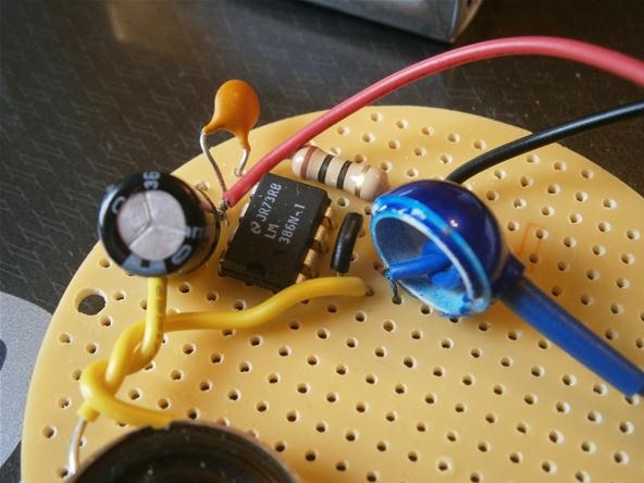
The LM386 datasheet has some useful example circuits for creating amplifiers. We will be making the simplest one, the 20 gain amplifier. The chip diagrams can be a little confusing. The triangle represents the 8 pin LM386 chip at the center of out circuit. The pins are numbered around the chip 1 to 8, as shown.
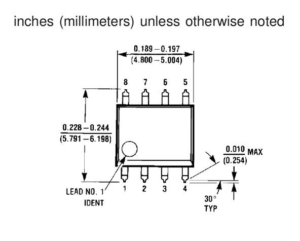
Use the corresponding pin numbers in the circuit at chip diagrams as a guide when wiring your circuit.
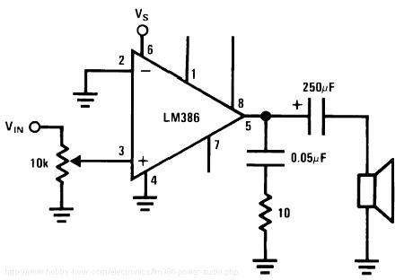
We will have to alter the capacitor values to the nearest standard values. Use a .047 uF ceramic capacitor and a 220 uF electrolytic capacitor instead of the values shown above.
In the breadboard layout shown here, the battery pack represents one 9 volt battery.
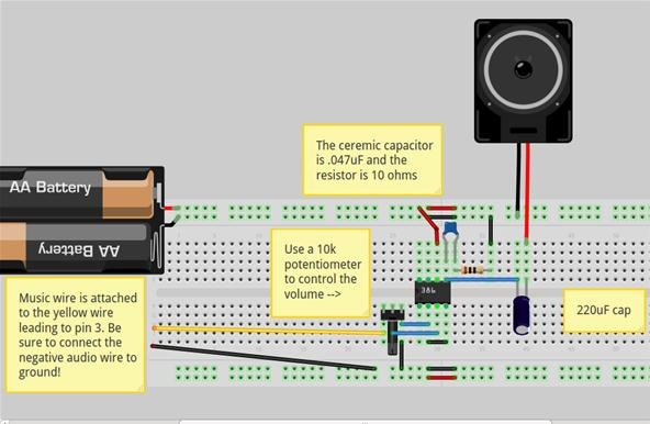
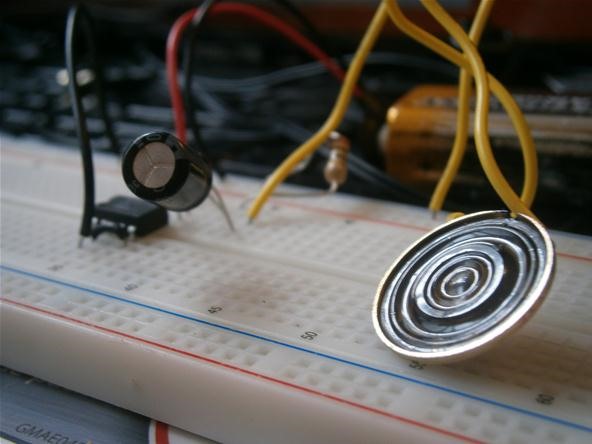
I used a tiny speaker for a compact board layout. You can use any size speaker rated at 8 ohms.
Step 2: Solder
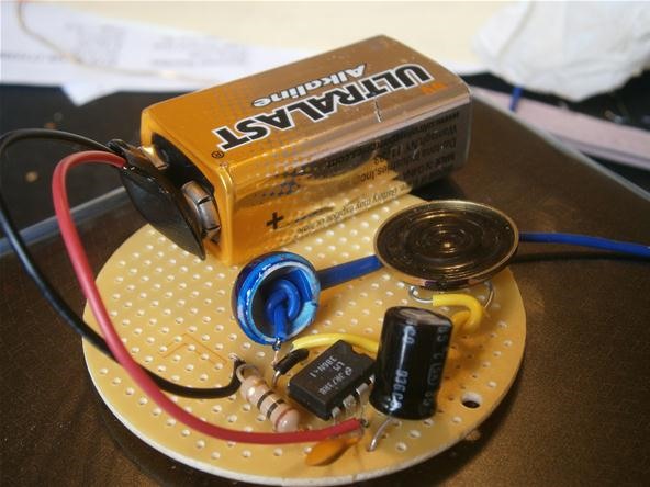
Place your components on the perfboard and bend the component leads to map out the circuit.Take care to leave enough room on your board for a 9 volt battery and speaker.
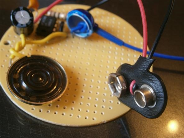
If you use a larger speaker, you can just tape the tiny amp circuit onto the back.
Step 3: Applications
You can use this circuit in any project where you need to amplify sound. You can use it as a headphone preamp, a portable guitar amp, an miniature MP3 player speaker, or even a synthetic robot voice box using the Speakjet.
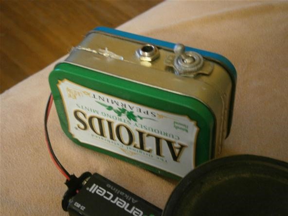
If you are going to house your amplifier in a tin, be sure to use electrical tape or heavy card stock to insulate the circuit from the metal bottom.
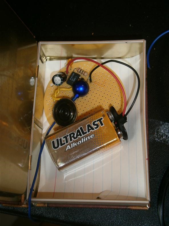
The enclosure makes all the difference! This speaker is for listening to audio books on long trips.

You can even fit your favorite MP3 player right inside with the amplifier!
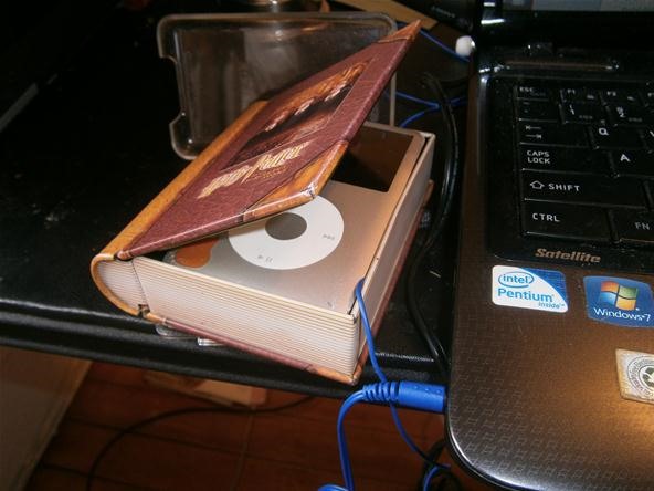
The book tin amplifiers make great gifts if you know your friends' literary tastes. I like to use these amps on my bike so I can listen to music without blocking out the noise of approaching cars.
Step 4: Printed Circuit
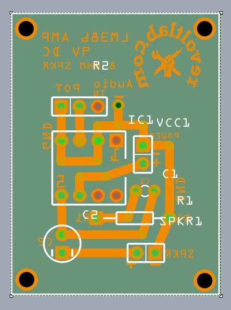
I took the liberty of preparing a printed circuit board design for this amplifier. Below you can see what the traces look like once they are etched onto a copper board. Note that this is not the image to use for laser printing etch masks.
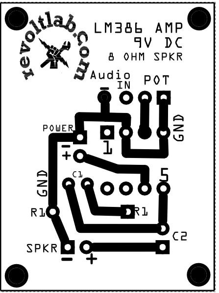
I added pin and trace labels in the copper etch to help in assembly. Note that the audio input wire from your headphones will solder directly to the input pin on the potentiometer.
I made the board in Fritzing with maximum trace widths for easy home etching.
Step 5: Guitar Amp
You can use this simple circuit as a portable guitar amplifier for rocking out on the street or porch. All you need to do is connect a 1/4 inch female audio jack to the audio input. Once the jack is soldered up, any standard guitar and cable can be plugged right in!
Be sure to use a large speaker and a sturdy enclosure to get your guitar amp to project well. Opening an closing the box while playing even changes the bass and treble levels!
If you have any questions, feel free to ask them in the comments below or in the forum. Don't forget to post your pictures and links to the corkboard so we can all see your awesome projects!
For more Mad Science fun, make sure to check out my how-tos for...
Just updated your iPhone? You'll find new emoji, enhanced security, podcast transcripts, Apple Cash virtual numbers, and other useful features. There are even new additions hidden within Safari. Find out what's new and changed on your iPhone with the iOS 17.4 update.


8 Comments
Where do you connect the 9 volt battery?
At the "power" connections where you see the + and - on the circuit diagram in step 4 above.
man what about this filter?
I found a TDA 2030 give a much better quality of sound and efficiency ... though you will need to use a 20k logarithmic pot to set the audio quality.
i made it perfectly but it give too bad sound
what should i do?
Looks great! I want to build one of these to install inside a cigar-box guitar, but would like to add reverb. Got any plans or Schematics for that!
Can you explain in more detail how this is supposed to work if I plug in my electric guitar? I have the 1/4 female jack that you say to put in the input to the potentiometer, but my guitar doesn't generate (and I don't think it should?) a voltage... Won't the voltage across the 10kOhm potentiometer just be 0V no matter what then, thus making the noninverting input to the op amp always equal to ground? I'm trying to follow your instructions, but I'm having trouble making sense of how it will work with a guitar.
Two questions:
1) I have two 32 ohm speakers. Should I hook them up in series or parallel
2) If I was to use a 200W speaker, are there any modifications that I would need to make?
Share Your Thoughts