
Whether you're in an airport, restaurant or waiting room, the insidious grip of televisions on human life is omnipresent. Sometimes it's nice to talk to other human beings while looking at them directly—actually hearing what they have to say.
Thankfully, there's a DIY device called TV-B-Gone, which can help you bring back this wonderful pastime of acknowledging one another by turning off any and all TVs in the area—at any time! It can also help us prank our loved ones or confuse our teachers.
Materials
- Arduino microcontroller
- Infrared LEDs
- Button
- 220-ohm resistor
- Breadboard
- Jumper wires
Step 1: Understanding the Components
Before jumping right into building the circuit, let's take a look at the components and what each of them does, so you have a basic understanding of what's actually going on.
Arduino
Simply put, the Arduino microcontroller is a tiny programmable computer that can interact with physical objects. In our project, we're going to program the Arduino to interact with the television. To do this, we need to download the Arduino IDE. This is the program that lets us write and load code onto the Arduino controller.
This is a really wonderful platform for beginners, and I urge anyone who thinks it's too hard to get into electronics to start here. Arduino makes it simple to blink lights, make tunes, and use all kinds of sensors. For now, all you need to understand is that the Arduino is programmed via USB using the Arduino software.
Infrared LED
An infrared LED, or light emitting diode, is an electronic component that shines infrared light when current is applied to it. Because infrared light is outside the visual range for humans, we cannot see it. However, most digital cameras can translate this light into a visible purple color.
The IR LED is the only component in this circuit with a polarity. That means that all of the other components can go into the circuit in any orientation, as they work in either direction.
Resistors
A resistor is a component that resists the flow of electricity. It essentially takes in electricity on one side and releases a smaller amount on the other.
For this experiment, we'll need the resistor to protect our infrared LED. The output voltage on the Arduino is too large and would damage the IR LED. By placing the resistor in the circuit with the LED, we reduce the load on the LED to a manageable size. The 10k resistor is a "pull-down" resistor in this circuit. We will use it to make sure the Arduino does not get confused when our button bounces up and down upon pressing.
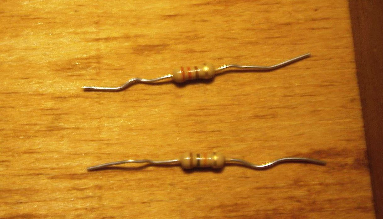
The colored stripes indicate their values. Check out this chart to determine the values of your resistors.
Button
The button is rather a straightforward component. When we press the button down, two points of metal are connected together and electricity flows through. When we release the button, those metal contacts are separated again and the circuit is broken.
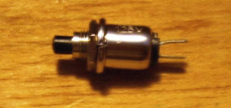
We will be breaking and connecting a circuit to tell the Arduino when we want to turn a television on or off.
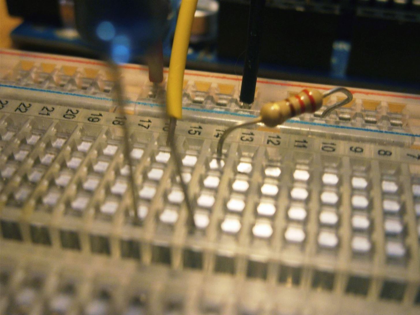
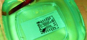
Breadboard
A breadboard is simply a means of creating circuits without having to solder wires together. It allows us to make the TV-B-Gone without making permanent mistakes. Along the side of the breadboard is a red rail for positive voltage. This is where power for the IR LED will come from.
Next to it is a black rail for negative or ground. This is where our circuit must end if it is to be connected and allow electricity to flow. The rows coming out sideways from the center of the breadboard are connected horizontally, but not vertically. By selectively placing components in these rows, we can electrically connect the correct pieces and separate the others.
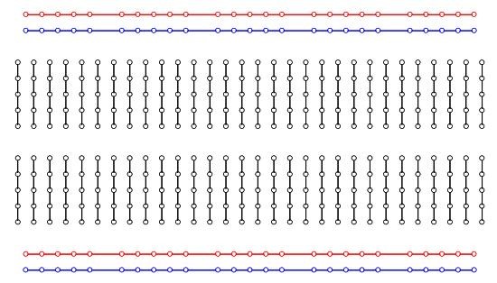
Above, you can see the metal traces that connect the holes underneath the breadboard. Putting two component leads into one of the vertical lines pictured will connect them electrically.
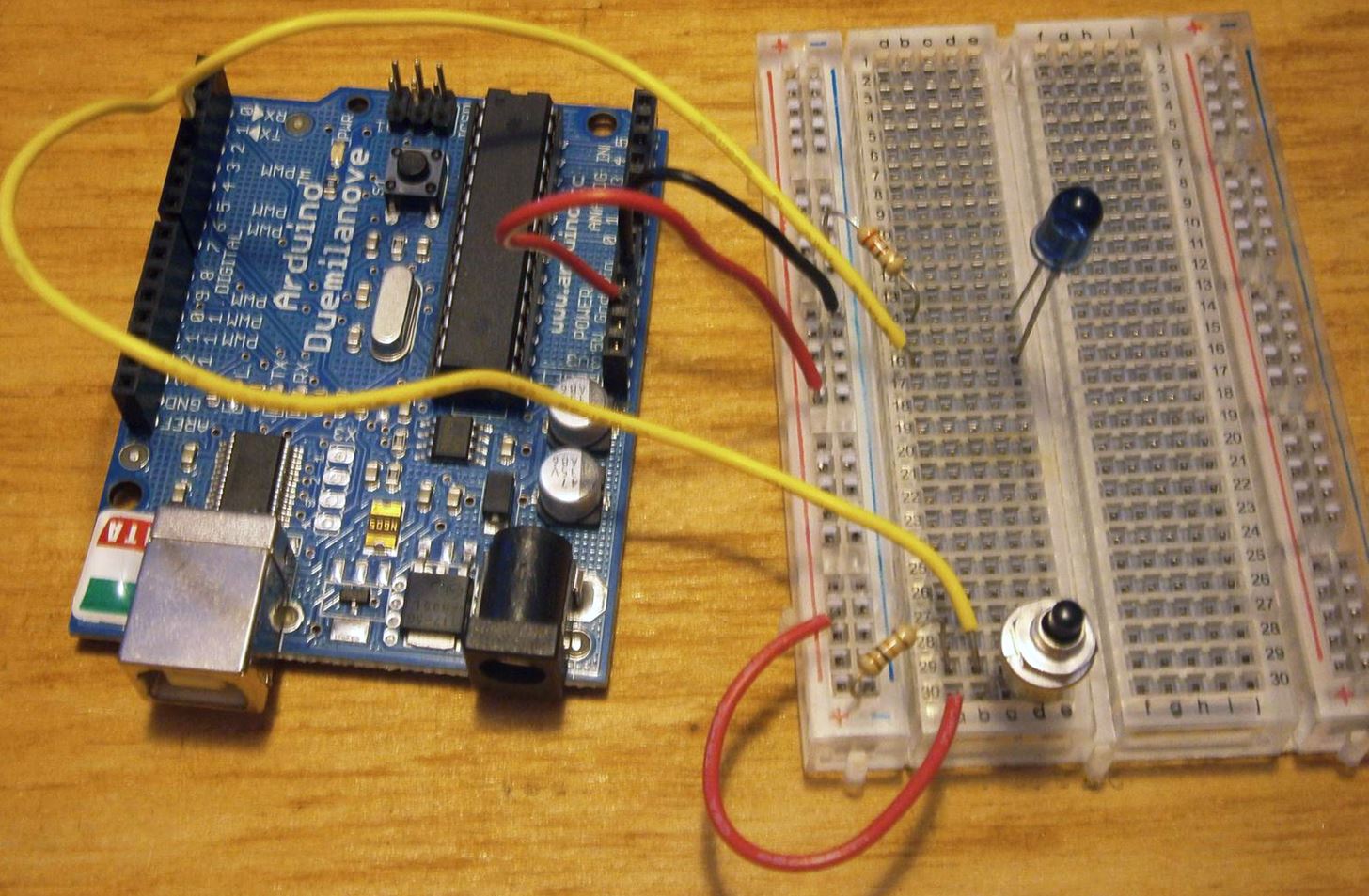
Step 2: Building the Circuit
Set your breadboard and Arduino beside each other. Connect the 5-volt pin from the Arduino to the red power rail on the side of the breadboard. Connect the ground on the Arduino to the black rail on the side of the breadboard.
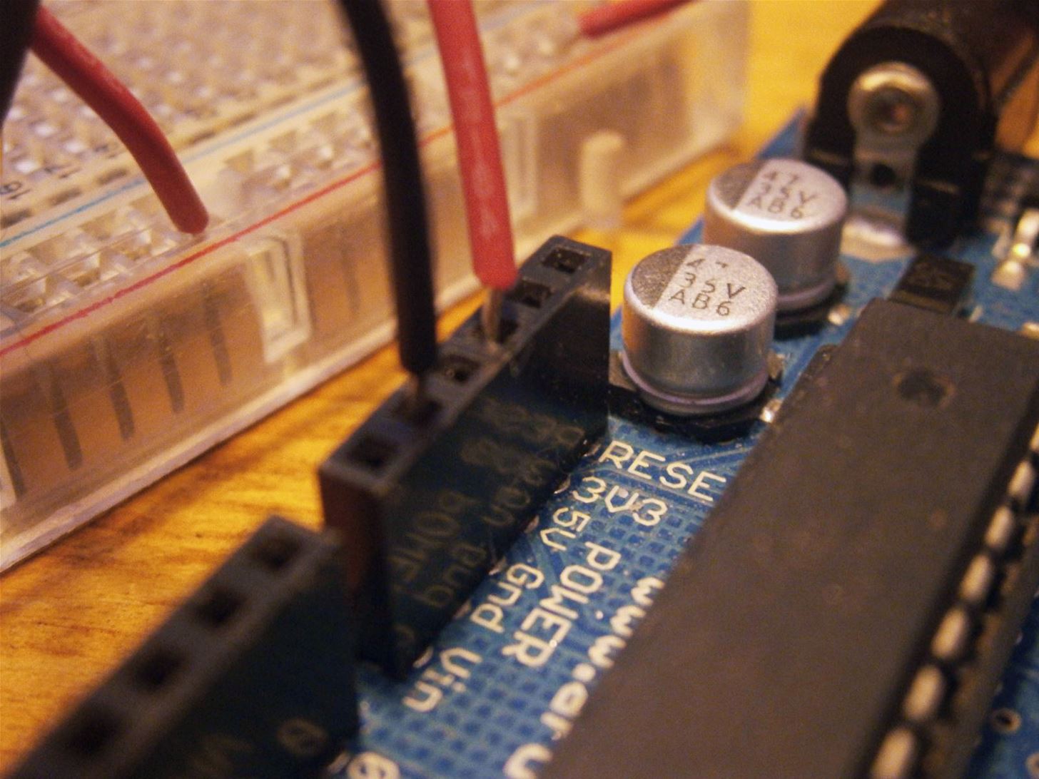
Place the IR LED on the breadboard so that each leg rests in a different row. The negative side has a shorter lead, while the positive side is longer. Connect the positive side to digital pin 3 on the Arduino. Place the 220-ohm resistor so that it connects the negative side of the IR LED to ground on the breadboard.
Place your push button on the breadboard away from the IR LED. Connect one leg to pin 2 and the other leg to the power rail on the breadboard. Where pin 2 connects to the button, use the 10k resistor to connect to ground.
Step 3: Loading the Code
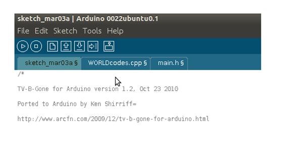
Connect the Arduino to your computer with a USB cable. Download this zip file containing the code for the TV-B-Gone. Open the TVB.pde file and paste its contents into the main window in the Arduino environment.
On the top right-hand side of the window, there's a button with an arrow pointing to the right. This button creates new tabs in the program's window. Click it and name the tab "main.h". Open the main.h file from the zip folder and copy/paste the contents into the "main.h" tab. Make another tab for the "WORLDcodes.cpp" file and copy paste its contents into that tab. Your program now has all the information it needs to run properly.
To make sure everything is working, press the play button on the top-left of the window. If the code compiles correctly, you should get a "Done compiling" message at the bottom. Click the right facing arrow, this time at the top left of the screen. This is the upload button. Press this button to load your program onto the Arduino.
Step 4: Try It Out!
Now that your code is loaded, bring your TV-B-Gone to the nearest television. Point the IR LED at the TV and press the button.
Infrared communication is a little odd. We could not have simply shone a constant infrared light at the TV. The IR receiver in a television set detects infrared light only when it is blinking at a certain frequency, usually around 38khz or 38,000 times per second. In this way, the TV cannot be interfered with by naturally occurring infrared light from the sun. The variations in the frequency determine which command is relayed to the television.

The TV-B-Gone code contains all of the most common pulses that turn on and off television sets. When you press the button, it plays them all one after the other.
Now that your TV-B-Gone is working, you can unplug it from the computer and power it with a 9 volt battery. Find a cool case to keep your meddling under the radar and have fun!
Just updated your iPhone? You'll find new emoji, enhanced security, podcast transcripts, Apple Cash virtual numbers, and other useful features. There are even new additions hidden within Safari. Find out what's new and changed on your iPhone with the iOS 17.4 update.


36 Comments
i love arduino :D
Me too!
So cool. Reminds me of when I was a kid, I had a Casio watch with a universal TV remote built-in. It didn't automatically send all the common frequencies though. I remember memorizing the codes for Sony, Panasonic, and Zenith TVs so I could change the channel on all the sports TVs in public places to cartoons.
Do you remember the brand of the watch? I'd love to find one.
Casio. Looks like they still make them...
awesome! and how come you can add links into your comments but we cant
People with comment scores above 10 can add links in comments. I'll PM you to show you how.
no way! (adds comment)
so cool sir
Thanks sir!
Where is the best place to purchase the materials for this project, ebay? I am quite intrigued what I could do with one of those microcontrollers! :)
Or home depot i guess
sparkfun.com is a good source
Too bad you can't make one to silence the Ultra Low Frequency Bass that keeps vibrating the fillings in my teeth whenever some guy with a loud stereo pulls up next to me at a light.
you could try an EMP :D
hmmm. but then your own car will stop working too!
Is there a schematic to go along with this? I usually just solder the pieces together instead of using a breadboard. Thanks
here is a link to a shematic that uses a transistor to make the IR signal more powerful:
thanks!
Happy to help!
It's the arduino UNO right
No. I was using the duemilanove.
Gotcha.
can i use two 10 k resistors instead of a 22k
so is it ok to use two together and if so, is it ok
to be 2 k out
Sorry for the confusion. You need a 220 ohm resistor and a separate 10,000 ohm resistor.
Two things have occured to me about this device. The first is that you don't actually need the arduino. I could use an ATTiny 13. I just need a simple boot loader to give it the program. The other thing is that it can be used to triger traffic lights the same way emergency vehicals do. It is just a matter of getting the blinking right. If you put a pot on the circuit and use it to amp up the frequency slowly, you can essily discover the signal. As a matter of fact you can use a 555 circuit to do that. Just stop when the light sensor flashes at you. Dial that in and you have it. It should work for almost any sort of device that uses an IR reciever. For the record, I would not recomend doing the traffic light thing. It can get you into trouble.
The IR Led is a 940nm or a 880nm? Becouse I've got just the 940 at home.
Hi! great guide! I'm trying to do the same thing with an Adafruit trinket, not sure if it is possible on a hardware level yet, could you tell me how big the code is? Cheers!
im getting this error
Arduino: 1.6.1 (Windows 7), Board: "Arduino Mega or Mega 2560, ATmega2560 (Mega 2560)"
In file included from main.h:1:0,
from tvbfull.ino:33:
tvbfull.ino:78:30: error: variable 'NApowerCodes' must be const in order to be put into read-only section by means of '_attribute_((progmem))'
tvbfull.ino:79:30: error: variable 'EUpowerCodes' must be const in order to be put into read-only section by means of '_attribute_((progmem))'
Error compiling.
This report would have more information with
"Show verbose output during compilation"
enabled in File > Preferences.
I have this issue, swell.
How easy would it be to do away with the button and have the code just cycle every x amount of minutes?
I would love to hide the box at someone's house when I visit and see how mad it makes them! (sorry I have a sick sense of humour)
How easy would it be to do away with the button and have the code just cycle every x amount of minutes?
I would love to hide the box at someone's house when I visit and see how mad it makes them! (sorry I have a sick sense of humour)
How easy would it be to do away with the button and have the code just cycle every x amount of minutes?
I would love to hide the box at someone's house when I visit and see how mad it makes them! (sorry I have a sick sense of humour)
im getting this error
Arduino: 1.6.1 (Windows 7), Board: "Arduino Mega or Mega 2560, ATmega2560 (Mega 2560)"
In file included from main.h:1:0,
from tvbfull.ino:33:
tvbfull.ino:78:30: error: variable 'NApowerCodes' must be const in order to be put into read-only section by means of 'attribute((progmem))'
tvbfull.ino:79:30: error: variable 'EUpowerCodes' must be const in order to be put into read-only section by means of 'attribute((progmem))'
Error compiling.
This report would have more information with
"Show verbose output during compilation"
enabled in File > Preferences.
hello there ...... i wanted to know if we can make tv-b-gone able to change the channels forward and backward???????????????
Sure, you just have to find the right codes to send... there are a lot of android apps that have a full db of remotes, here's one open source for HTC one (actually, the link is for the db itself). The database is well ordered, if you get the codes for channel + / - (or any other button really) and insert in the arduino code, that should work.
To open the database, you can use SQLite Spy, then go to Codetypes table, you'll see that chan + has ID 15 and chan - has ID 16, now go to codes table, and on the white box on top write
select * from codes where codetype_id == 15 OR codetype_id == 16
and press F9 ... now you have all the chan + / - for all remotes in the db .. it's 49.000 + results ! (yeah, you might want to clean it up a bit...)
Now copy the codedata ( that string that looks like eF6rVkorSsxNVbKKttQxN9Cx1DHGRZhjYeFUYmhuYUScSjQWGoGQMDQzMo7VAbo2tbA0NS+5UsnK2MLA0lRHqSC1KDM/RcnKAMYMyc9JLUrMS04FixWlFqQmljjnl+aVKFkZ1QIAOnw42A==) and write this on a linux shell
echo eF6rVkorSsxNVbKKttQxN9Cx1DHGRZhjYeFUYmhuYUScSjQWGoGQMDQzMo7VAboDM/RcnKAMYMyc9JLUrMS04FixWlFqQmljjnl+aVKFkZ1QIAOnw42A== | base64 --decode | openssl zlib -d
you will get something like
{"frame":9,70,9,30,9,30,9,30,9,30,9,30,9,70,9,30,9,70,9,30,9,30,9,30,9,30,9,70,9,30,9,1782,9,70,9,30,9,30,9,30,9,30,9,70,9,30,9,70,9,30,9,70,9,70,9,70,9,70,9,30,9,70,9,1623,"frequency":38095,"period":0,"periodTolerance":0,"repeatCount":2}
(took me a while to decypher, but it was fun)
yay... raw codes ! But those are specific for irda API of android (remember, we got this database from an android app), so you have to find out how to convert them to seemingly raw codes. Well, either you find out youself, or ask the author, here is the thread on XDA, once you know the formula to convert those, it's all done.
Consider scripting everything with some bash script or python... you don't really want to copypaste 49k codes by hand.. SQLitespy was just a start to give an overview of the database structure.
And make sure you report back here how to convert those codes to arduino compatible ones ! That would benefit everyone...
Happy coding !
Share Your Thoughts