

Making your own circuit boards can be a daunting challenge. You have to design a schematic, test it on a breadboard, design the board layout, and then after all of that, you still have to print and etch a board!
Luckily, we have Fritzing.
Fritzing is a free open-source PCB design suite that works on Windows, Mac, and Linux. Unlike Eagle or KiCad, Fritzing has a simple and realistic interface that makes designing circuits intuitive. Today, I'm going to show you how to use my favorite design program to make your very first professional circuit board.
Step 1 Download and Install Fritzing
Go to the Fritzing download page and select your operating system. Follow the instructions on the page to install on your computer. When you install Fritzing, it will come with all sorts of great parts libraries. There are basic components like wires, buttons, resistors, etc. There are also specialty components like Arduino boards and sensors that can easily added to your designs!
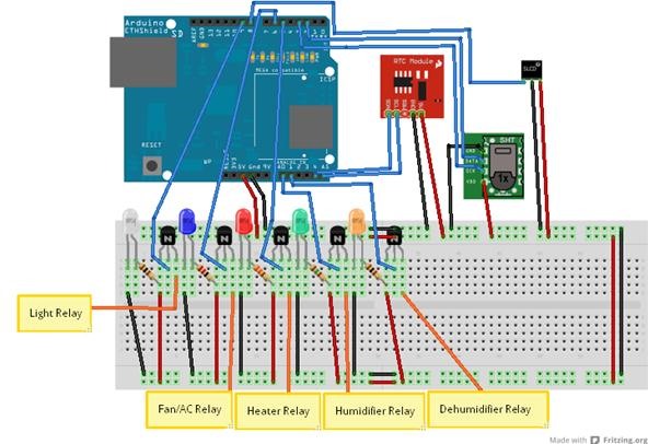 Image by ArduinoGRC
Step 2 Getting Started
When you first open a Fritzing project, you will start on the breadboard screen as shown below.
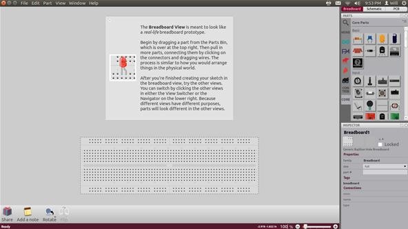
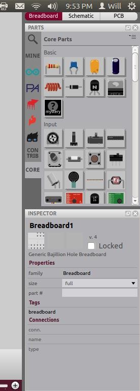
To the right of the screen is our menu bar with all of the components and options. If a component is customizable, the lower half of the tool bar will display the custom options available for that specific part.
The first thing we want to do is place a component down on the breadboard. We will be designing a simple circuit that powers an LED light. We will need one resistor in our circuit. Select and drag the resistor onto the work area as shown below. The introductory text box above the breadboard will disappear when you place your first component.
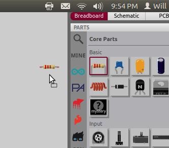
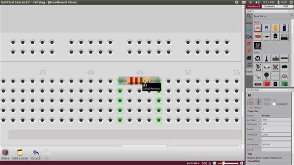
Drag the resistor down to the breadboard so that each lead is connected to a vertical column on the board. When a component makes a connection to a column, the whole row turns light green as shown below. The green area indicates an electrical connection between breadboard holes.
Step 3 Customizing Parts
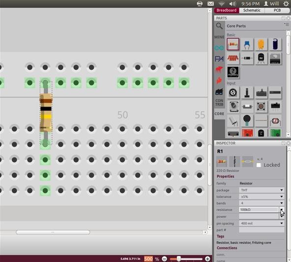
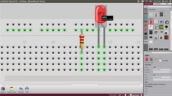
With our resistor selected, we can use the options in the lower half of the toolbar to change the value, tolerance, and spacing of the resistor. Set the resistor to 220 ohms. Below, the resistor has been rotated to make a connection with the ground rail on the top of the breadboard. To rotate any component in the breadboard, schematic, or board layout tab, simply right-click and select rotate. I rotated this resistor 90 degrees clockwise.
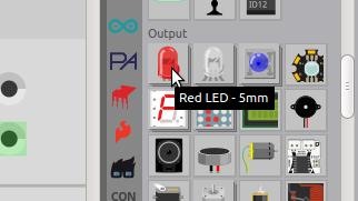
Next in the circuit comes an LED light. Click and drag the LED component from the tool bar on the right to the work area.
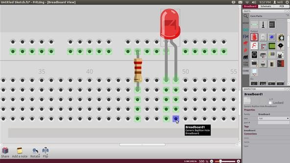
Place the LED on the board next to the resistor as shown below. So far the resistor and LED are not connected to power or to each other. Notice that the green lines are not touching.
Just like a real breadboard, we can add small wires to make the connections we need. Place your mouse over a breadboard hole and observe that it turns blue. This means it is ready to start a wire.
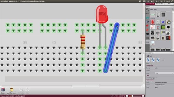
Click the breadboard hole and drag the new wire to the desired location. Below, we connected the positive end of the LED to the uppermost breadboard row.
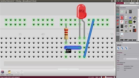
Click and drag to create another wire connecting the negative side of the LED to the resistor. That's it. Our main circuit is all set up!
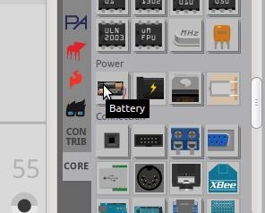
To finalize the design, we need to add some power. Click and drag the battery component from the toolbar on the right into the work area.
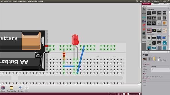
Position the power wires, as shown below, with positive on the top rail and ground on the bottom rail. The wire spacing of the battery output does not fit with the spacing of the upper breadboard power rails. To fix this, place the red wire over a hole in the top row. Now, click and drag a wire from the negative battery lead to the lower row. Your battery connection should look like the picture below.
Congratulations! You designed an entire circuit and all it took was dragging and dropping a few components! The breadboard feature is not found in any other PCB design software. It really makes the whole process easier to be able to see real life images of your circuit.
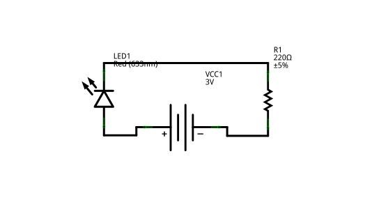
Step 4 Schematic
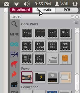
While you were clicking away on the breadboard screen, Fritzing was busy making you an exact schematic of your circuit! Select the schematic button on the upper right hand of the screen.
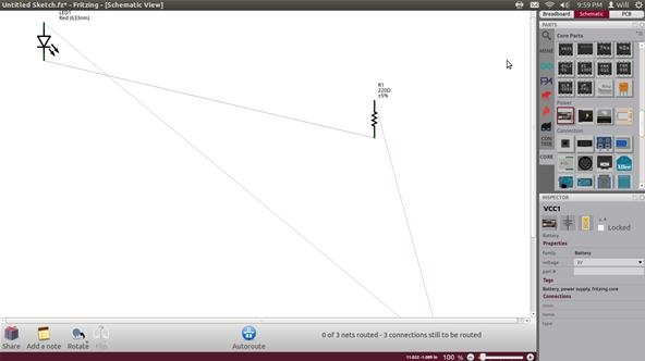
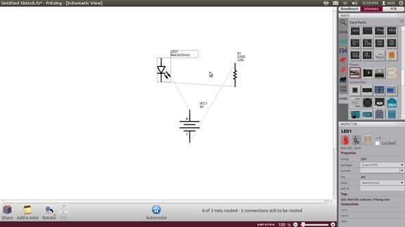
Ta-da! It's your schematic! Well, it's at least technically your schematic. Fritzing makes sure that all of the connections are correct, but aesthetics are still beyond the grasp of a desktop app. Your screen will look like the one below with the components spread well apart. Some may even be off screen! Zoom in and out using the slide bar on the bottom right of the work area.
Once you find all your components, drag them together and zoom in so you have a reasonable view of the mess.
My connects all started out crossing over each other. We want to orient the components so that the lines between them are as short and straight as possible. Right-click and use the rotate option to orient your components in a saner fashion.
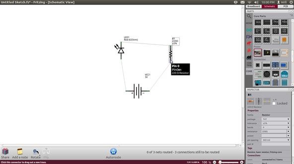
Once the lines are direct and clear, compact your schematic as much as possible.
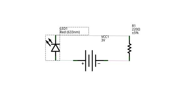
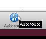
Once your schematic looks as compact as the one above, click the Autoroute button at the bottom center of the workspace.
Bam! A perfect new schematic for sharing your design with others and documenting your epicness for posterity.
Step 5 Circuit Board Layout
We made it! We are finally going to design a real life circuit board on our own! Click the PCB tab on the top right of the tool bar. As with the schematic tab, the PCB tab has our components scattered hither and thither.
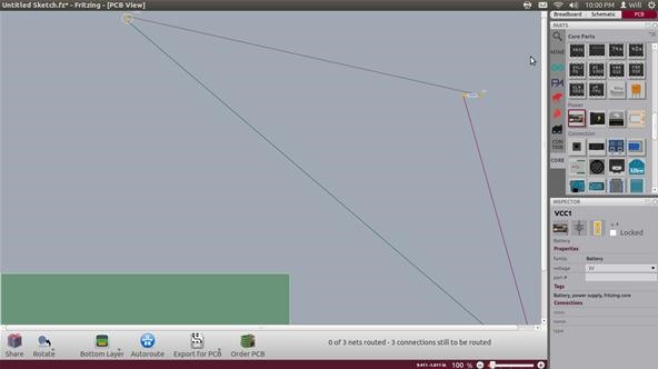
Zoom out with the slider on the bottom of the screen and make sure you can see all of your parts.
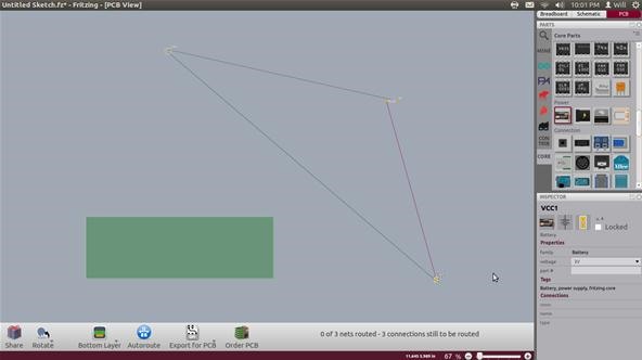
Drag them together like we did with the schematic components. Drag them all onto the green board and zoom in.
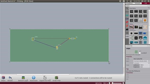
Since the purpose of a circuit board is to make circuits take up as little space as possible, we are going to shrink the green board down until there is just enough space for the components. To shrink the board, simply click on any corner and drag toward the center of the board.
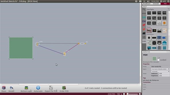
As with the schematic, move and rotate the components so that the lines between them are straight and direct as shown below. These lines are not yet the copper traces on the final board design, but indicators as to what parts need to be connected.
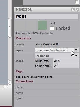
Click on any part of the green board and bring your mouse to the lower half of the tool bar where the board customization options appear. Go the the "layers" scroll down menu and select "one layer (single sided)" Circuit boards made in big factories can have lots of layers of traces sandwiched into the board. Because our circuit is simple and because single-sided blank PCB boards are common and cheap, we will design our copper PCB traces on a single layer.
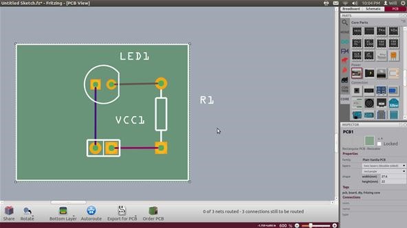
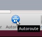
After selecting a one-sided board, click the Autoroute button in the bottom center of the work area.
Our copper traces have magically replaced the thin lines!
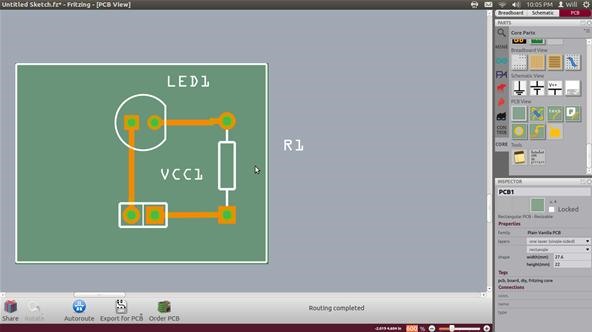
Right now, you technically have a fully functioning circuit board design and you can go on to etching a physical board at home. But before you waste a copper clad board, take a few minutes to make sure your board works the first time and looks as cool as you are.
Step 6 Cleaning Up Your Board
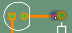
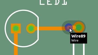
The Autoroute created some superfluous bend points in the topmost wire. Bring your mouse over any of the tiny orange circles on the wire. When the bendpoint turns blue, right-click and select "remove bendpoint".
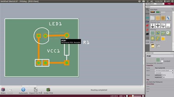
Below, the top wire is selected and is free of bendpoints! Straighter traces mean more consistent etching.
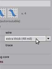
Select the wire and bring your mouse to the lower half of the toolbar on the right side of the screen. There is a wire option for customizing the width of the copper traces on your board. Small traces are good for intricate designs and for saving space, but home PCB fabrication cannot always produce small and accurate traces. To make sure the connections are strong even if a small part of the etching process goes wrong, select the largest trace width from the dropdown menu.
The traces below are now robust enough to deal with some imperfections in the fabrication process.
Now that it works, and works well, it is time to add your own style to the board!
Step 7 Customize Your Board
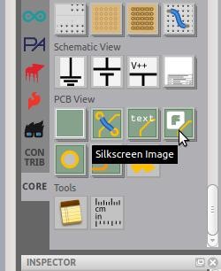
Custom text and images are easy to load into any Fritzing project. In the tool bar on the right scroll all the way down to the options titled "PCB View". The rightmost option with the letter F is the silkscreen option. Click and drag it into the work area.
The silkscreen layer is essentially a layer of labels painted onto a board after the circuit is built. You may have noticed that there are already silk screen images of each component on the board. Fritzing will always automatically create the component silk screen layer!
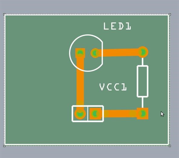
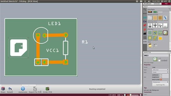
Below we have placed the default silkscreen image on our board. It appears white because it is part of the silkscreen layer and not the orange copper layer. But someone shrieks, "I thought we were doing this project at home! We can't hand paint this tiny stuff on a circuit board!" Right you are, keen concerned scientists. Instead of adding a silkscreen image, we can add a copper image to be etched just like we plan to do with the traces.
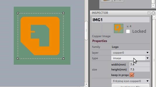
With the silkscreen image selected, go to the lower half of the tool bar and select "copper0" from the "layer" dropdown menu. Your image will turn orange indicating that it is part of the copper layer. It will also flip horizontally. The entire copper layer is, in fact, completely backwards. Fritzing does because when we etch the final board, the whole pattern is reversed in the transfer from the paper to the copper surface.
To upload your own image, click the image file button below the layer, type, and size customization menus on the lower toolbar. Below, I added in my website name and logo as well as some simple text. The text as of now is not customizable with regard to font. Fritzing is still in development though, and I wouldn't be surprised if custom fonts where available soon.
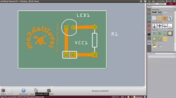
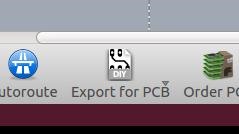
This is it! Are you ready? We made a circuit on a breadboard, we designed a schematic diagram, we customized our final board layout, and now we get to reap the rewards! After checking everything over, click the "Export for PCB" button at the center bottom of the work area.
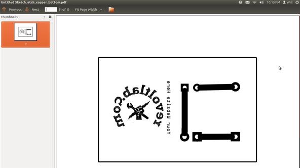
Save the files wherever you like and minimize your Fritzing window. Navigate to the new files and open them up. The files will be in PDF form which is good because it means we know our image is the right size. The first file will be a mask of your copper layer. This includes the circuit and any images we included in the copper layer. Notice that the image is still reversed.
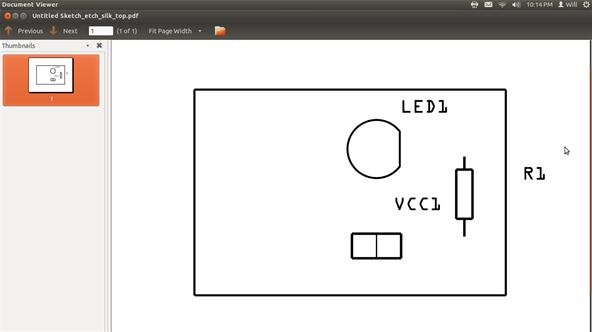
The other file is the silkscreen mask. If you were to send your design off to a PCB factory, they would ask for both of these files and print them up without trouble. For the home fabricator though, the silkscreen file is useless.
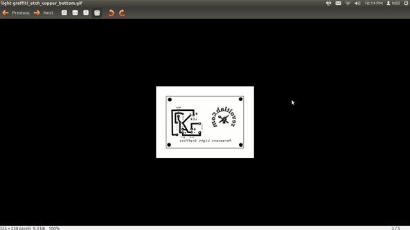
To get an editable file, I convert my PDFs to GIF files using the GIMP image editor. Once I have the design in GIMP, I can put a whole set of PCBs on an 8.5" X 11" sheet of paper. Below is the PCB design GIF for my permanent light graffiti. Notice that it appears life size in this full screen capture. Never scale your circuit image up or down! The component holes will become distorted and your parts will not fit in the board!
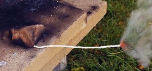
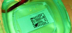
There you have it! You can send these files off to a factory and get professionally made circuit boards designed by you! If designing your own board has given you a power rush and you need to be able to do the whole process with your own bare ruggedly individualistic hands, check out my article on home PCB etching.
I really hope this helps all of you Mad Scientists get into circuit board design. I was put off by the esoteric CAD programs at first, but Fritzing really is PCB design for the utterly noobish.
Did This Help?
Did this article help you? Are you having a problem with Fritzing or any circuits in general? Post a comment below and I will work for you to get your design out of your brain and into reality. Start a discussion in the forum if you have general questions about this or any project. I am always happy to help out a comrade scientist.
Don't forget! We are accepting entries for a chance to win a full lucid dreaming kit! All you need to do is share one of your project photos on the Mad Science corkboard. All entries are welcome. Be sure to post by the end of May for your chance to win. Submitting is simple as pie. Check out my example entry here.
Just updated your iPhone? You'll find new emoji, enhanced security, podcast transcripts, Apple Cash virtual numbers, and other useful features. There are even new additions hidden within Safari. Find out what's new and changed on your iPhone with the iOS 17.4 update.


5 Comments
This is a really excellent tutorial. You've made something that's typically very intimidating to get into feel accessible. Thank you!
Thanks Bryan!
one word " excellent'
hello, i was working with Fritzing, and riding my circuit on a breadboard, and I opened the schematic to see how it looks, everything was in order, there you continue to build the circuit on the breadboard, and when I opened the schematic, was all out of order. ASK, keeping the two in order, in a stirring should change the other, but one is different from another, how to make the two are equal? schematic and breadboard?
thank you
Eduardo
miragempro@hotmail.com
Hi, I was working with Fritzing. I want to add some component that can't found at the menu bar like GSM/gprs Shield icomsatv1.1. How could I add this GSM shield into the fritzing? urgent... pls help me anyone... Thanks =)
Share Your Thoughts