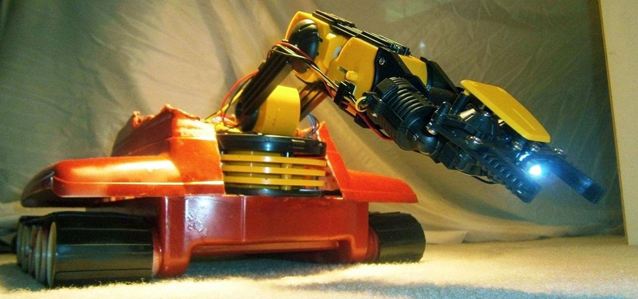

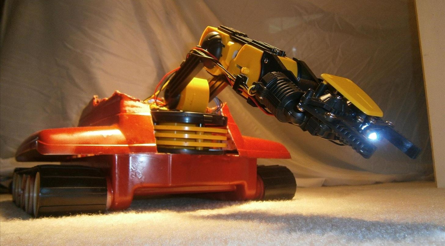
War leaves a lot of stuff behind. Torn families, delegitimized institutions, mass graves, and unexploded ordinances litter the post occupation landscape. Whether or not you have driven the imperialist out, or are still in the phase of armed resistance, you will need the ability to safely diffuse bombs. My bomb defusing Silvia-bot can do it all. She can catch grasshoppers, cut wires, collect samples, tase enemies and even play chess!
Materials
- Robotic Arm Kit
- Chassis (RAD Robot base)
- (4) SPDT relays
- Perfboard
- (2) Switches
- Momentary push button
- Tin
Step 1: Assembling the Robotic Arm
There isn't much to this step. The OWI robotic arm edge kit comes with a complete set of instructions, including 1:1 ratio images of all the parts for easy component identification. Give yourself an afternoon to take this one on. It isn't complicated, but it is a bit finicky. Make sure your motor enclosures are screwed together tightly before activating the final robot arm.

Once you finish the arm, you will undoubtedly feel compelled to robotically manipulate objects all around your house. This is okay, take some time to enjoy the accomplishment.
Step 2: Chassis
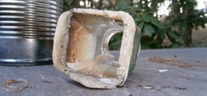
You will need to find a chassis large enough to hold the robotic arm and stable enough that it won't fall over when the arm is flailing around. Luckily, I snagged a broken RAD robot at a flea market for 5 bucks! It has tons of room for the arm, a wide base, and it even has tank treads! I only had to remove the upper humanoid section to make room for the arm.
Inside the base are two gear boxes and six wires. Two wires bring power to the robot, two wires power the left motor, and the last to wires power the right motor.
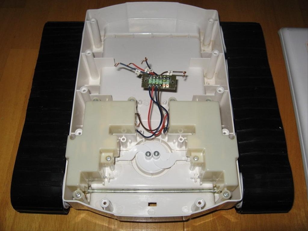
Image by EZ Robot
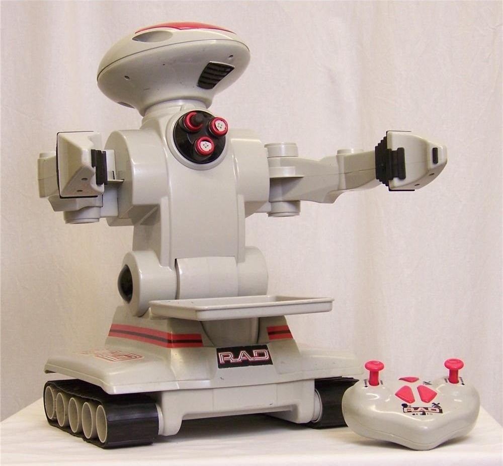
Image by Oxfam
Step 3: Which Wire Do I Cut!?
Really, you don't need to cut any wire, but you do need to figure out which wires go to the motors. The black and red wires are the power wires from the battery. We don't need these and you can cut them off if you want them out of the way. The remaining four wires connect to the two motors.
Connect the four wires in turn to a battery to find out which pair of wires control which motor. Once you have two wires for the same motor, experiment with attaching the wires backwards to reverse the direction of the motor. Do this with both motors to ensure that the gears, motors, and treads are fully functional.
Step 4: H Bridge Relay Style
Now that we know our motors can turn in both directions, we need to create an H bridge that will allow us to switch directions at the flip of a switch. In this article, we used a premade H bridge chip to simplify the process. This time around, we will get more acquainted with H bridge theory by building our own from scratch using relays.
If you remember from our previous H bridge article, an H bridge is a circuit that allows us to reverse the polarity of a motor, thereby changing its direction.
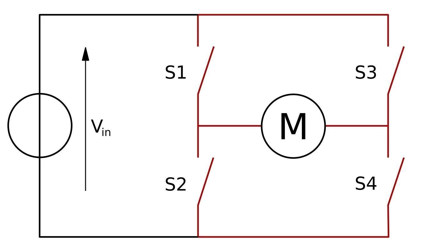
Image by WCyril BUTTAY
Notice the four switches surrounding the motor in the image above? When S1 and S4 are connected, the motor spins one way. When S3 and S2 are connected, the motor spins in the opposite direction.
Instead of using 4 switches for each motor, we will use two single pull, double throw (SPDT) relays. An SPDT relay is like a switch that has two on states. A traditional switch flipped one way turns on a light and flipped the other way turns off the light. An SPDT relay flipped one way connects one side of the motor to power and flipped the other connects the other side of the motor to power. Using another relay to switch the grounded side of the motor, we can control the direction of the motor.
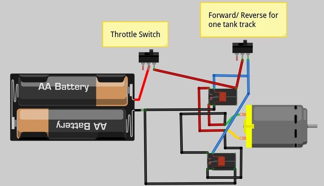
Above, the throttle switch controls all power going into the system. If you don't hit this switch, nothing will work. The switch on the right is used to reverse the direction of the motor. If you follow the blue wires, you will see that they are bringing power to the relay coils . When this second switch is flipped, power flows into the relay coils, flipping the internal switch and reversing the motor just like in the first four switch diagram.
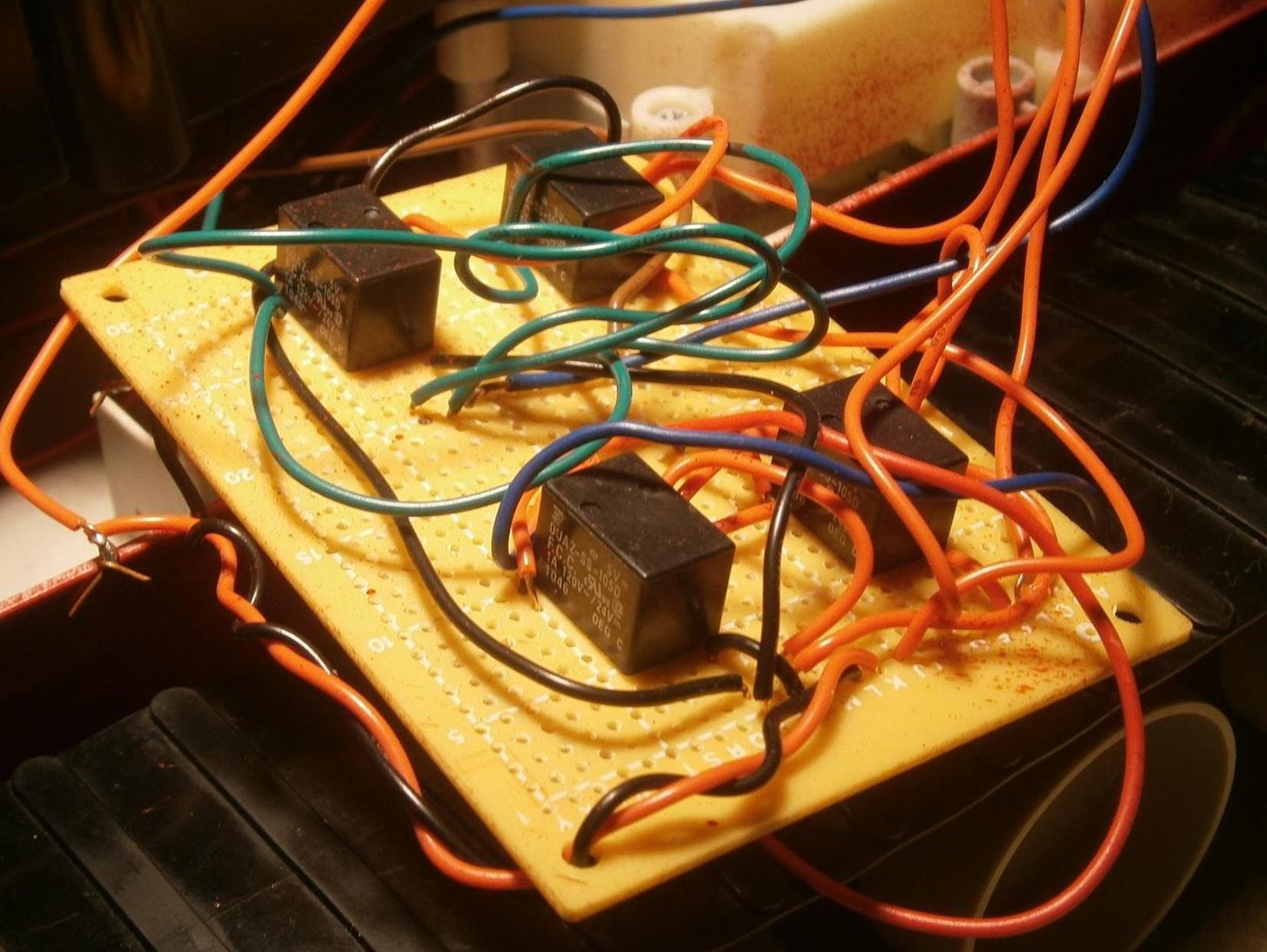
Create this circuit two times with a total of two motors and four SPDT relays. Be sure to connect them to a common power and ground.
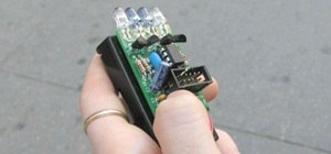
Here is what my board ended up looking like.
Note that the throttle switch works better with a momentary push button. This allows you to brake the bot simply by releasing the button, cutting power to the motors and relays.
Step 5: Mount the Arm
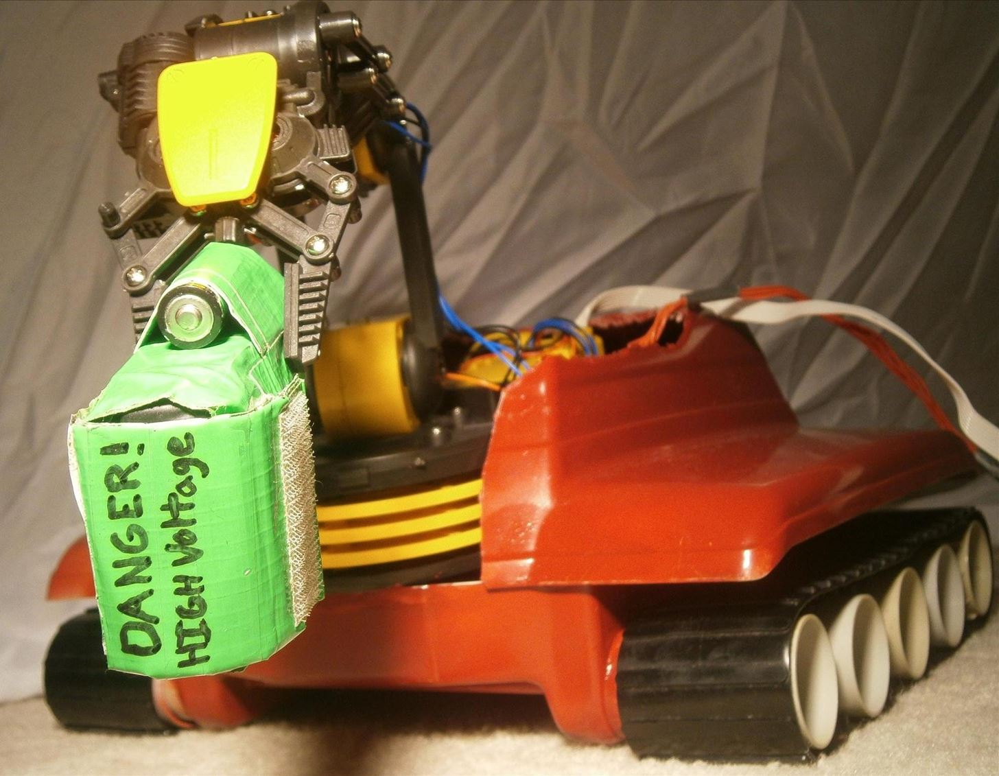
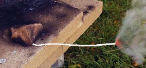
Now that the motor control is set up, we can install the robotic arm onto our chassis. I simply hot glued each corner to the tank base. It holds well even when crashing into walls and setting off mousetraps.
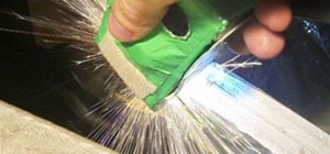
I had to modify part of the shell to fit the robotic arm. I cut the center of the tank cover using a soldering iron and pliers. I recommend using a hack saw if you have one handy. Burning plastic lets off some nasty fumes.
Step 6: Power!
Luckily for us the 4 D batteries powering the robotic arm have plenty of punch to get our tank tracks turning. Solder the power and ground connections on the robotic arm to the main power and ground rails on your relay board. Hold down the momentary push button and your motors should start turning. Play around with the left and right track switches to get the hang of two track control.
Step 7: Controller
The robotic arm comes with a pretty nifty controller already. Five switches control the shoulder, elbow, wrist, and gripper on the arm. All we need to do is add the momentary throttle button and the two tank track switches to the control box. I decided to mount the tank control in a separate enclosure. This makes it possible to have two operators simultaneously, doubling the fun of disarming ordinances.
Six wires lead from the base to the tank controller. There are two wires for each switch: the momentary throttle button, the left track switch, and the right track switch.
Step 8: Paint
I painted my Silvia-bot red for revolution, and because it was the only color of spray paint I had. Be sure to cover up any parts you don't want to get paint on. Plastic bags work well for paint protection.
Step 9: Hell Ya! A Robot!
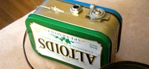
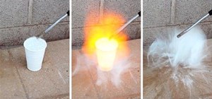
Now that you have your robot in one functional piece, it is time to set it to work! I had hours of fun defusing mousetraps, playing chess, collecting rock samples, and tasing Altoids tins.
Some other possible uses include defusing bombs, tearing down bee hives, spraying wasp nests, disposing of kitchen biohazards, disposing of unexploded fireworks... the list is endless. Check out this video of Silvia-bot in action!
That's me singing a song I wrote in the first half of the video.
Thoughts
The next step for this bot is a remote control for safer disarming of bees and bombs. What else should we add to Silvia-bot? Ideally, Silvia-bot will one day be an autonomous Earth rover, perhaps searching for water, methane gas, or radiation. For now though, I prefer taking out the mouse laden traps with the bomb bot.
Just updated your iPhone? You'll find new emoji, enhanced security, podcast transcripts, Apple Cash virtual numbers, and other useful features. There are even new additions hidden within Safari. Find out what's new and changed on your iPhone with the iOS 17.4 update.


1 Comment
How much is the Chassis (RAD Robot base)
Share Your Thoughts