


Lying is awesome. From a very young age, children learn that flat out denying the truth gets you out of trouble and helps keep you calm in the face of horror. But what happens when you just have to know if someone, say, used your toothbrush? You could ask them to take an expensive and arduous polygraph test.
If you're industrious and don't have the dough for a legit polygraph, you can make your very own galvanic skin response (GSR) device. These devices are one of many connected to a real polygraph machine. The GSR device measures the conductance of your skin. When you are nervous, under stress or in pain, your skin sweats very slightly, thereby increasing the conductivity.
Today, we will make a cheap GSR device and learn if our toothbrush is really safe after all.
Materials
- Arduino
- Aluminum foil
- Velcro
- Wire
- 10k resistor
- Breadboard
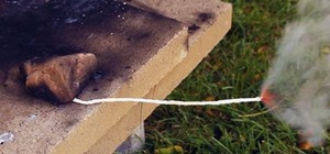
Step 1 Make the Electrodes
GSR machines require an even and consistent connection to the skin in order to function properly. To keep surface area and pressure constant, we will make tin foil electrodes to wrap around two fingers of the interrogated.
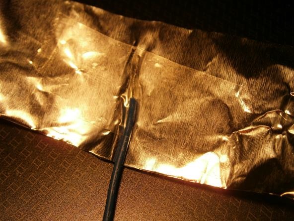
Begin by taping the exposed end of a wires to a sheet of foil.
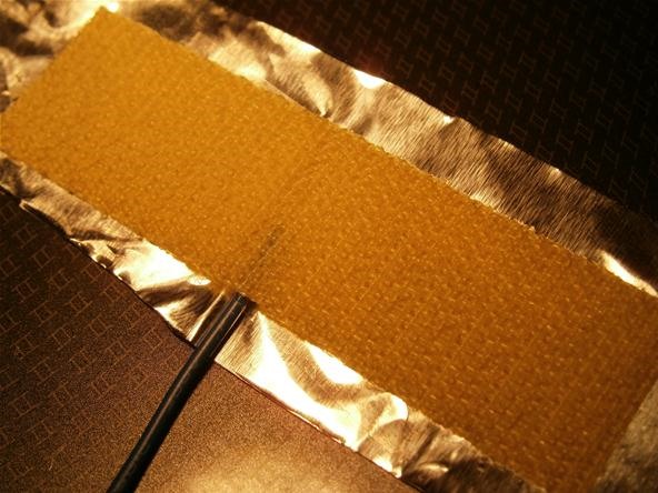
Adhere a strip of Velcro over the tape and cut off the extra foil.
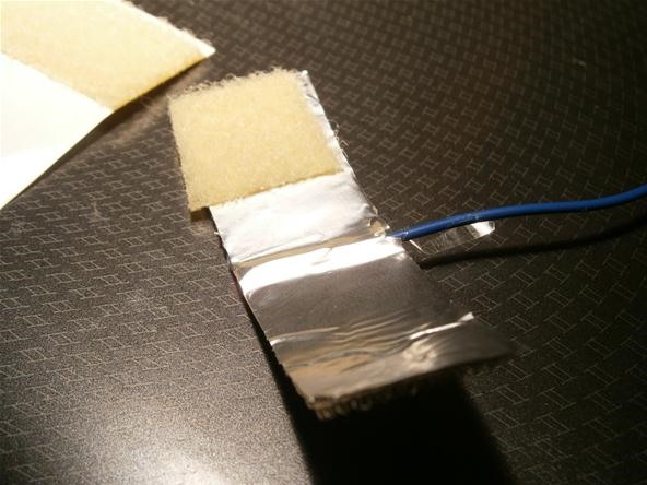
Last, add a single piece of Velcro at the end of the foil side. Be sure you are using the right side of the Velcro sheet.
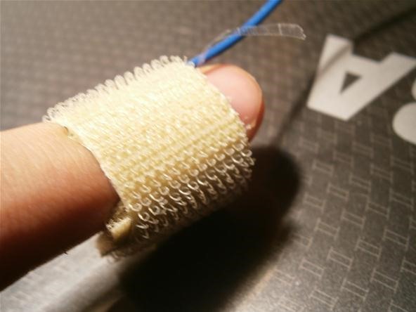
Now you have an electrode that wraps perfectly around your finger.
Step 2 Wire the Circuit
Wire the circuit according to the diagram below. We are essentially making the finger electrodes into an analog input. The grey wires represent the finger contacts. The resistor has a value of 10k ohms.
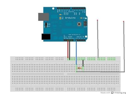
Take note that the sensors are connected to analog input 0 on the Arduino.
Step 3 Load the Code
We can just use the example "Graph" code that comes with the Arduino software. Navigate to File>Examples>Communication>Graph. This program takes the analog values coming from the skin and sends them to be graphed so we can see them change over time. Load the code onto the Arduino and put on the finger electrodes.
If you do not have the Processing application, it is free to download here. Copy and paste the processing code from the Arduino example into the processing application. The processing window should look familiar as the Arduino application is based off of it. Run the processing program. A graph should pop up. The height of the graph line represents the conductivity of your skin. The higher the line, the higher the conductivity, the higher likelihood that you are lying.

Please note that this device is by no means foolproof. Anything could make the subject nervous and sweat more. Do not use this device for life and death decisions!
Now we can interrogate anyone! Well, anyone we can convince to sit down and put these strange electrodes on their fingers. What would you do with this device? What uncertainties are nagging at you? If you try out this project, be sure to post up pictures and video on the corkboard. As always, any questions can be posted in the forum or sent to me directly.
Just updated your iPhone? You'll find new emoji, enhanced security, podcast transcripts, Apple Cash virtual numbers, and other useful features. There are even new additions hidden within Safari. Find out what's new and changed on your iPhone with the iOS 17.4 update.


36 Comments
Now to build the other polygraph inputs!
in the proccessing program it says, "the function begin(int) does not exist" what did i do wrong?
fixed it nvrmind
I'm having the same problem, how did you fix it?
Same issue. I just copied the source from the Arduino software over to the processing and pressed run. Anything else that's needs to be done?
I will check out the problem tonight after I finish version one of the automatic pet feeder.
I figured it out, i didn't read the code. You don't paste the full code from the arduino example, just the part that's commented for processing. That's what I get for blindly pasting the code.
Glad you found the problem. Can we see your lie detector when it's finished?
I don't see a power source for the Arduino. Make sure it's a battery for safety. Never plug a device that connects to the body to a power source that derives it's power from a high voltage source.
The arduino runs of the usb connection to the computer. No need to fear.
you're still having an electrical connection with mains power via ground.. batteries should be the way to go
what arduino I have to buy for these project
I used the duemilanove but the newer Uno should be fine.
Does it matter what kind of wire or breadboard I use?
nope
Where do I find the arduino example?
Open the arduino program on your computer and navigate to File>Examples>Communication>Graph
Is the arduino program the one that can be downloaded above? because I could not find communications in that program
Yes. The Processing sketch is commented out within the arduino program. Copy the Processing code only from the arduino sketch and paste it into the Processing window.
Anybody know what the code is that I load onto the Arduino?
void setup() {
// initialize the serial communication:
Serial.begin(9600);
}
void loop() {
// send the value of analog input 0:
Serial.println(analogRead(A0));
// wait a bit for the analog-to-digital converter
// to stabilize after the last reading:
delay(2);
}
Whoo hoo - got the comm port issued solved. No output on the graph - gives my rxtx errors
Do you have any pictures or documentation I can look at?
how do we tell what board to buy
Some help. i wanna take this to college. I cant take my laptop, so can you tell me how to use just an LED to tell if you are telling a lie? And no processing and graphs. I am sure you can do it
Hi! I'm a novice at robotics to say the least and really wanted to do this for my science fair. I actually don't really understand using Arduino and I was wondering if you could go a bit more in detail about Step 2 and Step 3? I'm getting confused on how to wire the circuit based on the diagram and I try yet can't get the code listed to run in Processing. Your probably rolling your eyes at my ditziness, but we all have to start somewhere!
In Processing 2, when I input the code, it says that it can't find anything named serial (Line: Serial.begin(9600);). did anyone else have this issue?
did u ever resolve this issue?
My graph isn't showing anything at all, all the programs are set up, do you know what I did wrong?
how to see the ouput of lie detector on graph??? how to code it??
My daughter is trying to use your diy polygraph for her science fair project. We are having problem know which part of the Arduino Graph code needs to be copied to the Processing application. Can you help?
Um, will an aluminium foil work?
So both resistors get connected to the resistor?Does the 0 terminal go to the opposite side of the resistor ?Does the wire from the resistor, the black one, go to the other black wore off of the ground? Also where does the red wore go, the 5 v terminal. Thanks.
How do you make the graph come up on the screen, I have tried many things but I cannot get it to work right.
A black window pops up but there is no output. I have copied the exact code and have processing 3.5.4
My daughter got the blank black screen. I traced the problem to this graph code:
Serial.list() returns an array of ports. The index starts at 0. The code comments show the first port at position 0 being used. When fed to println, Serial.list() prints all of the available ports, delimited by spaces.
On my kid's computer, a bluetooth port was first, and thus the blank screen. Her Arduino uses the second port in the output, so the fix was to change it to use the second item in the array, which is at index position 1. I changed this:
myPort = new Serial(this, Serial.list()[0], 9600);
to this:
myPort = new Serial(this, Serial.list()[1], 9600);
If yours is not graphing output, look at the output in the Programmer, and verify you're using the correct port index position. This will have to be done every time new graph code is added via the IDE , unless there's a way to modify the example graph template code to reflect the proper port index for your environment.
Hope this helps someone.
Share Your Thoughts